Remote Control Glider
- cepkarate
- May 24, 2020
- 7 min read
Updated: Aug 3, 2020

This is one of my first projects. I decided to design and build a simple RC glider for outdoor leisure flying. The remainder of this post consists of my progress on this project.
PROCESS
Because this was my first time designing and building an RC glider on my own, I needed to do some heavy research on the electronics and materials needed for the build. The following list is the basic order of progress on a project, which will be used for my later projects as well.
Determine what type of plane I want
Research and find what materials and electronics I need
Calculate the approximate weight of the electronics
Approximate the total weight
Find the correct aspect ratio for the correct wing cube loading based on the type of plane I want to build
Calculate the dimensions of the horizontal and vertical stabilizers based on the optimal horizontal and vertical tail volume ratios
Determine the location of the aerodynamic center, center of gravity, and neutral point to ensure fly-ability
Since I chose a glider, the wing cube loading (WCL) should be between 3 and 4.99 (Meyers). The wing cube loading is a numerical way to classify the type of plane based on flight characteristics. The design of the airplane was based on this characteristic.
ELECTRONICS
The biggest step of this project was researching the specifications of all the electronics. Knowing my total weight goal of the glider to be a maximum of 2 lbs (907.2 g), the minimum power output of the motor in normal flight conditions should be approximately 140W; therefore, the motor I selected was capable of more than 140W (E-Flite). In fact, the website that I bought the motor from, Horizon Hobby, recommended the motor I chose - Park 450 Brushless Outrunner Motor - be paired with a 20A electronic speed controller (ESC) and a 3s battery which outputs 11.1V. The ESC I bought operates at 30A; I chose this so the ESC doesn't get overloaded if the motor peaks at 20A. By pairing the ESC and battery I chose, the motor should peak at 222W (given, 11.1V * 20A = 222W), the absolute theoretical maximum. This is ideal since the motor will be operating on about half capacity in flight. (This theory will be tested in flight once the glider is built.)
Once the motor, ESC, and battery were selected, the servos and propeller were found. The propeller must be matched to the Kv rating of the motor and the type of aircraft. The Kv rating is the revolutions per minute, rpm, of the motor at 1V with no applied load. The rating of the motor I bought is 890Kv which is on the lower end for a glider, therefore, the propeller I chose is a decent size and has a steeper pitch, to produce enough thrust. The propeller I ordered was 9x6, meaning it is 9 inches in diameter and would move 6 inches forward in one rotation if it were moving through a solid. (I also bought a 12x4 propeller for fun and comparison in flight tests later on.) The servos I chose were standard 9g Nylon gear servos.
The following table is a list of all the electronics I bought for the RC glider. (Note: Some materials I already had in the shop and are not listed in the table)

Table 1. Electronics
ASSEMBLY
After I measured the weight and dimensions of each component, I assembled the electronics to make sure they work properly together. The videos of the assembly below showcase this process. This was my first time doing large scale soldering, therefore it was quite difficult to work quickly and accurately at first. "Slow and steady" was the mentality for this process.
(Videos will be coming soon!)
All of the electronics worked wonderfully. However, the motor made a series of beeping sounds which was diagnosed as the motor indicating it was not receiving a signal from the ESC. This was fixed by reversing the setting for the motor on the transmitter and re-calibrating the connection between the two. Once this was fixed, all the servos, motor, and transmitter were working properly together.
DESIGN & CALCULATIONS
(Note: All of the calculations for tail volumes, dimensions, and aerodynamic centers were done on paper by hand.)
After all of the electronics had been weighed, measured, and tested, the design of structure and shape of the glider was to be done. I decided to use pine wood for the frame and light foam board for the control and lifting surfaces, and chassis. Using these materials together helped to keep the total weight of the plane down. Before calculating the optimal dimensions of the wings, horizontal and vertical tail, boom, and chassis, a rough, basic design was done to approximate the total weight of the glider to use in the calculations. This approximate weight was 850 grams (30 oz); the rough design I made projected 800 grams, therefore I added a buffer of 50 grams for the connections, adhesives, design error, etc.
The first thing I calculated was the wing area given the range for wing cube loading, WCL.
WCL has the standard units of ounces per cubic feet. I decided to target the highest WCL rating for a glider, which is 4.99, because I wanted to build a plane that is as stable as a glider but is capable of some aerobatic performance. Using Equation 1 below, I determined the wing area should be approximately 475 square inches.

475 square inches for the wing area seemed rather large to me if I needed to maintain a high aspect ratio, therefore I decided to make the wing area smaller and design a more effective horizontal tail. I chose to design the wings with a chord of 8.67 inches and span of 50 inches, including the fuselage, making the wing area to be 433.5 square inches. I also designed the wings to have a dihedral of 5 degrees, so that the glider has roll stability in light crosswinds.
The next step was to calculate the area and dimensions of the horizontal tail that will add to the effectiveness of the glider's lift and control. The horizontal tail area should be 25-35% of the wing area for a large glider. The horizontal tail volume, V_H should range from 0.35 to 0.75, where the higher the ratio, the more effective the tail is. Therefore, my goal was to have a decently high V_H of 0.65 for the tail to be effective but not overpower the wings.
After several educated guesses on the dimensions for the horizontal tail, the optimal V_H was found to be 0.6537 using Equation 2, with a span of 18 inches and a chord of 6.66 inches. In Equation 2, l_t stands for the distance between the center of gravity and aerodynamic center of the horizontal tail; c_w is the chord of the wing; S_t and S_w are the areas of the horizontal tail and wing respectively. The aerodynamic center of the tail is at 25% chord, which is 1.665 inches behind the leading edge of the tail. The center of gravity was found in SolidWorks Assembly Mass Properties, located at 3.38 inches behind the leading edge of the wing.

Because the horizontal tail and vertical tail affect each other in the calculations for tail volumes, I had to calculate the tail volumes and dimensions of each about four times before reaching the optimal tail volumes, in this multi-variable problem. Since the vertical tail volume depends on the horizontal tail volume, the center of gravity and aerodynamic centers of the tails also had to be recalculated after every trial due to the changing weight at the end of the boom. Nevertheless, I was able to determine the ideal tail volumes and center of gravity.
The vertical tail volume, V_V, was found by using Equation 3 below. The aerodynamic center of the vertical tail is located at 2.40 inches behind the leading edge of the vertical tail. The range for the vertical tail volume is between 0.02 and 0.05, where the higher number means it's more effective. I decided to target a V_V in the middle of the range, around 0.035.

In Equation 3, l_F stands for the distance between the center of gravity of the glider to the aerodynamic center of the vertical tail. S_F is the area of one side of the vertical tail, and b_w is the span of the wings. The V_V ended up being 0.03413, which is very close to my goal.
Once the dimensions and ratios for all the control surfaces were calculated and optimized, the dimensions and characteristics of the plane were inputted in a .AVL file to be used for the calculation of the neutral point in AVL. This file is given below; note that .AVL files are not supported on Wix, therefore the .txt file is uploaded and can be converted by changing the extension.
Using the coordinates and data from the SolidWorks assembly of the glider, the surfaces and center of gravity were inputted into this file. All of the dimensions in this file are in SI units, meters and kg. The center of gravity is located at 3.38 inches (0.08585 m) behind the leading edge of the wings.

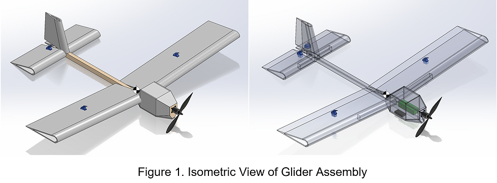
Figure 1 displays the isometric view of the glider assembly in SolidWorks. It also showcases the general location of the center of gravity. The following figures display the dimensions of the glider which were used in AVL to find the neutral point. All of the dimensions in Figures 2, 3, and 4 are measured in inches.


The total mass of the glider measured in SolidWorks is 875 grams (1.929 lbs), which is slightly below the maximum weight I intended. Because I estimated a total mass of 850 grams, the percent error in the dimensions I chose for the surfaces based off the WCL is 2.94%, which is rather low and will be ignored since it will not alter the fly-ability of the craft.
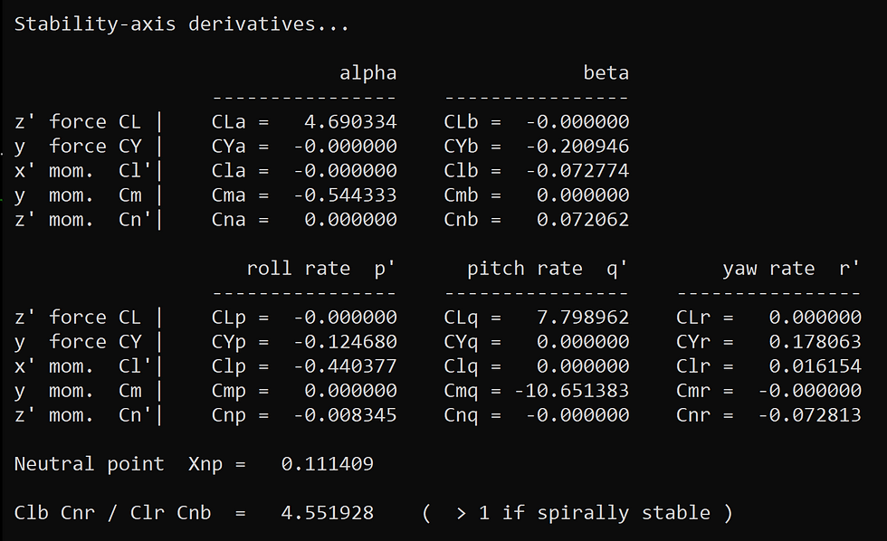
In AVL, I used the actual mass based on SolidWorks. The surfaces plotted by AVL are shown in Figure 5. From Xnp in Figure 6, the neutral point was found to be 0.111409 m (4.3862 in) behind the leading edge of the wing. The remaining stability derivatives are also given in Figure 6.

Figure 5. Surfaces Plotted by AVL

Figure 6. Stability Derivatives from AVL
According to FlyBoy38L from Flite Test, the neutral point should be 5-15% of the mean aerodynamic chord behind the center of gravity, where 5% is limited stability and 15% is great stability. Because the center of gravity, CG, is 3.38 inches behind the leading edge of the wing and the mean aerodynamic chord, MAC, is 8.67 inches, the neutral point on this glider is 12% of the MAC behind the CG. This means that the plane is very stable. The placement of the aerodynamic centers of the control surfaces, center of gravity, and neutral point are plotted in Figure 7 below, to showcase the stability of the craft; all measurements are in inches.

Figure 7. Location of Aerodynamic Centers, Neutral Point, and Center of Gravity
BUILD
I plan on building the glider within the next few weeks, since school begins shortly. Once the craft is built, I will fly and test the craft, and tweak the design if needed.
Stay tuned!
Comentarios